
Installing Mob-Connect & Mob-Full
Before you start
This guide covers the professional installation of the IturanMob system for Mob-Connect and Mob-Full. The install procedure is the same for both products — they share one system and one wiring layout. The only difference is CAN-Bus telemetry, which applies to Mob-Full only and is covered in its own optional section near the end.
This is a wired install that interrupts the starter circuit and taps the vehicle's lock and data wiring. It is intended for a qualified automotive electronics installer. If you have never wired an immobilizer or read a vehicle wiring map, stop and get help before cutting anything.
Read this first: Understanding what each part does before you make any electrical connection is the difference between a clean, one-time install and an expensive comeback. Read the System overview section even if you are in a hurry.
Tools you'll need
- Digital multimeter
- Wire cutters / flush cutters
- T-tap or insulation-displacement "scotchlok" tool for CAN wires only (a tool that taps a wire without cutting it)
- Electrical tape and heat-shrink
- Zip ties / cable ties
- Vehicle-specific hand tools: Phillips and flathead screwdrivers, torque driver, and panel/trim removal tools as needed for the vehicle you are working on
How the system works (what does what)
The IturanMob system is a single kit made of three main hardware modules connected together in a local network (analog, CAN Bus, and LIN), plus two relays and the vehicle harnesses.
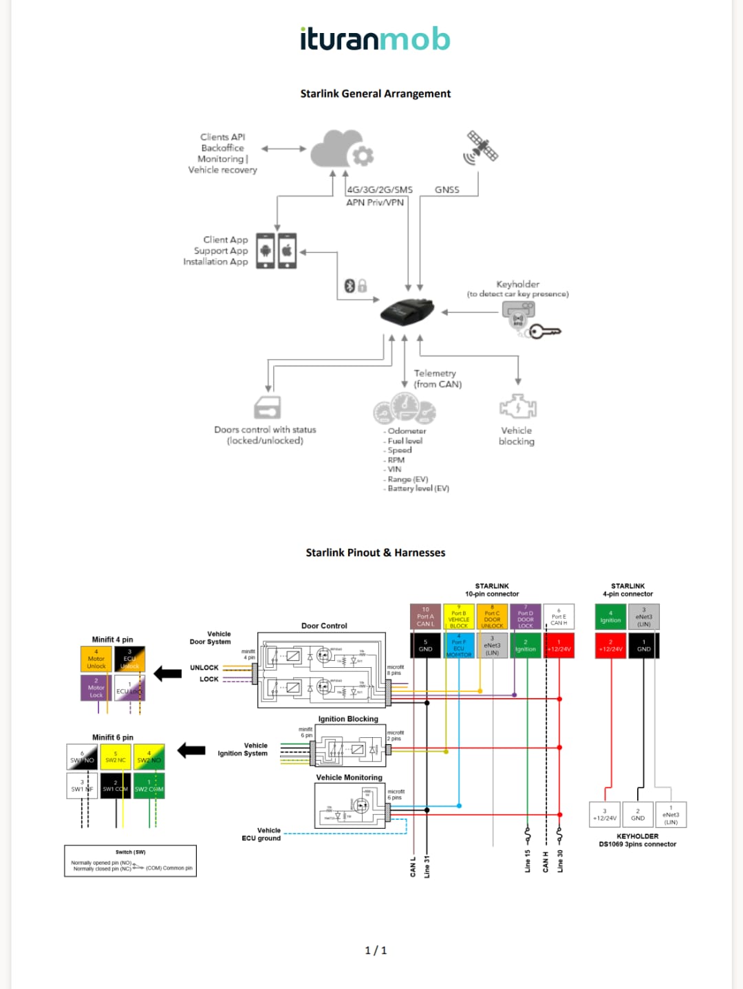
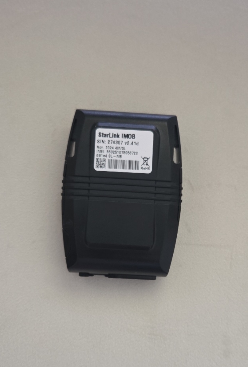
1. StarLink IMOB — the brain. This is the central processing, location, and communication unit. It handles GPS positioning, cellular data (4G/3G/2G with private APN/VPN), and has a built-in Bluetooth antenna. It receives commands from the cloud or the app and sends command pulses out to the peripherals — door lock/unlock and starter immobilization — and it reports vehicle information back to the cloud.
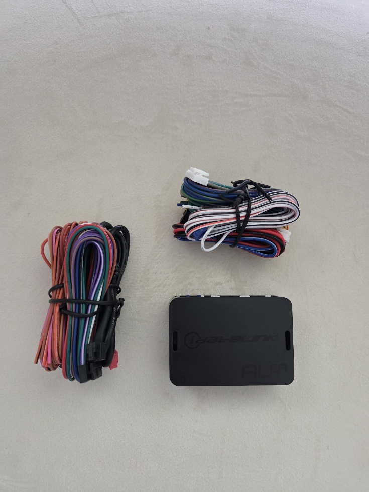
2. iDataLink module — the translator. The StarLink puts out analog pulses. The iDataLink interface receives those pulses and converts them into digital messages in the vehicle's original CAN Bus language. This lets the system lock and unlock the doors using the car's own factory command codes — so you do not have to run wires into the doors. It makes the whole install cleaner and faster.
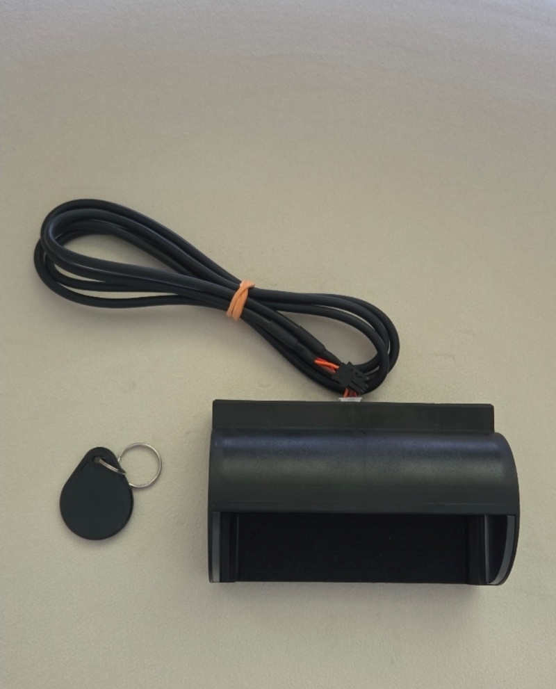
3. Key Holder — the key custody cradle. A hidden compartment that physically detects whether the vehicle's original key is present or absent. The included RFID Tag must be permanently attached to the key. When a renter returns the car and drops the key into the cradle, the Key Holder confirms the key is back and reports it to the StarLink over the LIN protocol (port eNet3). This is what lets the system know the car has been physically returned.
Golden rules of the hardware
These two rules are non-negotiable. Breaking either one will cost you the kit or the install.
Every central component is pre-programmed at the factory for ONE specific vehicle (year, model, and VIN). Because of the engineering parameters loaded into memory, the kit will not work on any other vehicle. If you try to install it on a different car, the network commands will not run correctly. Confirm the kit matches the vehicle before you open anything.
Never, under any circumstances, cut a CAN Bus twisted-pair wire. You tap CAN wires — you never cut them. (More on this in the field workflow below.)
The two relays
The kit ships with two relays. Tell them apart by size, wire colors, and function before you wire anything.
Door lock relay (the larger relay)
Works together with the iDataLink interface to lock, unlock, and arm the doors.
- Identify it: the larger, square-bodied relay with a purple, orange, and white wire harness.
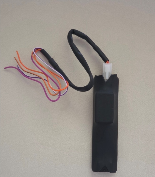
The iDataLink 4-pin Minifit connector controls the doors:
- Pin 1 — Purple/Black: ECU Lock (sends the lock command to the vehicle's factory module)
- Pin 2 — Purple: Motor Lock (drives the physical door-lock actuator)
- Pin 3 — Orange/Black: ECU Unlock (sends the unlock command to the vehicle's factory module)
- Pin 4 — Orange: Motor Unlock (drives the physical door-unlock actuator)
The iDataLink 10-pin main vehicle harness:
- Pin 10 — Red: constant direct positive (+12V), Line 30
- Pin 9 — Black: ground / negative (GND)
- Pin 1 — Pink: ignition input (post-key / +12V switched), the network's technical ignition feed
- Pin 3 — Brown/Red: CAN High (CAN H) — high-speed digital data wire
- Pin 4 — Brown/Yellow: CAN Low (CAN L) — the complementary data wire
Immobilizer relay (the smaller relay)
Cuts the engine start safely when a block command is active from the cloud or app.
- Identify it: the compact relay with a black, yellow, green, and white wire harness.
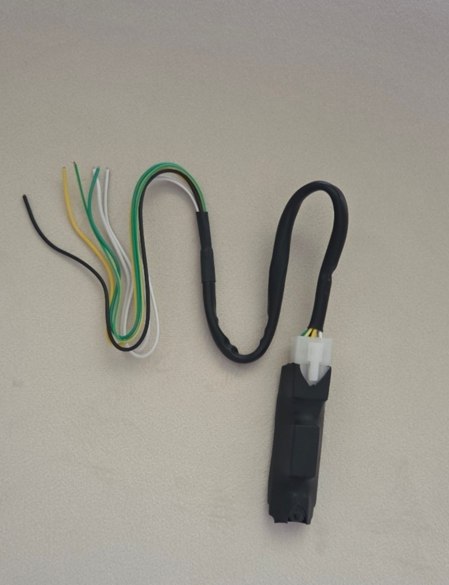
How you wire the block depends on the vehicle:
- Conventional-key vehicles: make a direct physical cut in the wiring that feeds the starter motor, and run it through the relay.
- Keyless / push-button (Start/Stop) vehicles: the block interrupts the Start/Stop button circuit instead, preventing the car from recognizing a start request.
Power and grounding
The main input harness comes with two in-line automotive blade fuse holders (purple and yellow fuses) to protect the hardware against shorts. Keep both in place.
Required connections:
- Line 30 — Red wire: direct positive (+12V / +24V)
- Line 31 — Black wire: negative / general ground (GND), connected directly to the original chassis ground point at the ECU
- Line 15 — Green wire: post-key (ignition) signal
Bench test before you install
Before you mount anything in the vehicle, build the whole system on the bench using the quick-connect connectors. This lets you confirm the topology and the physical layout of the full kit, and catch a bad connection while everything is still easy to reach.
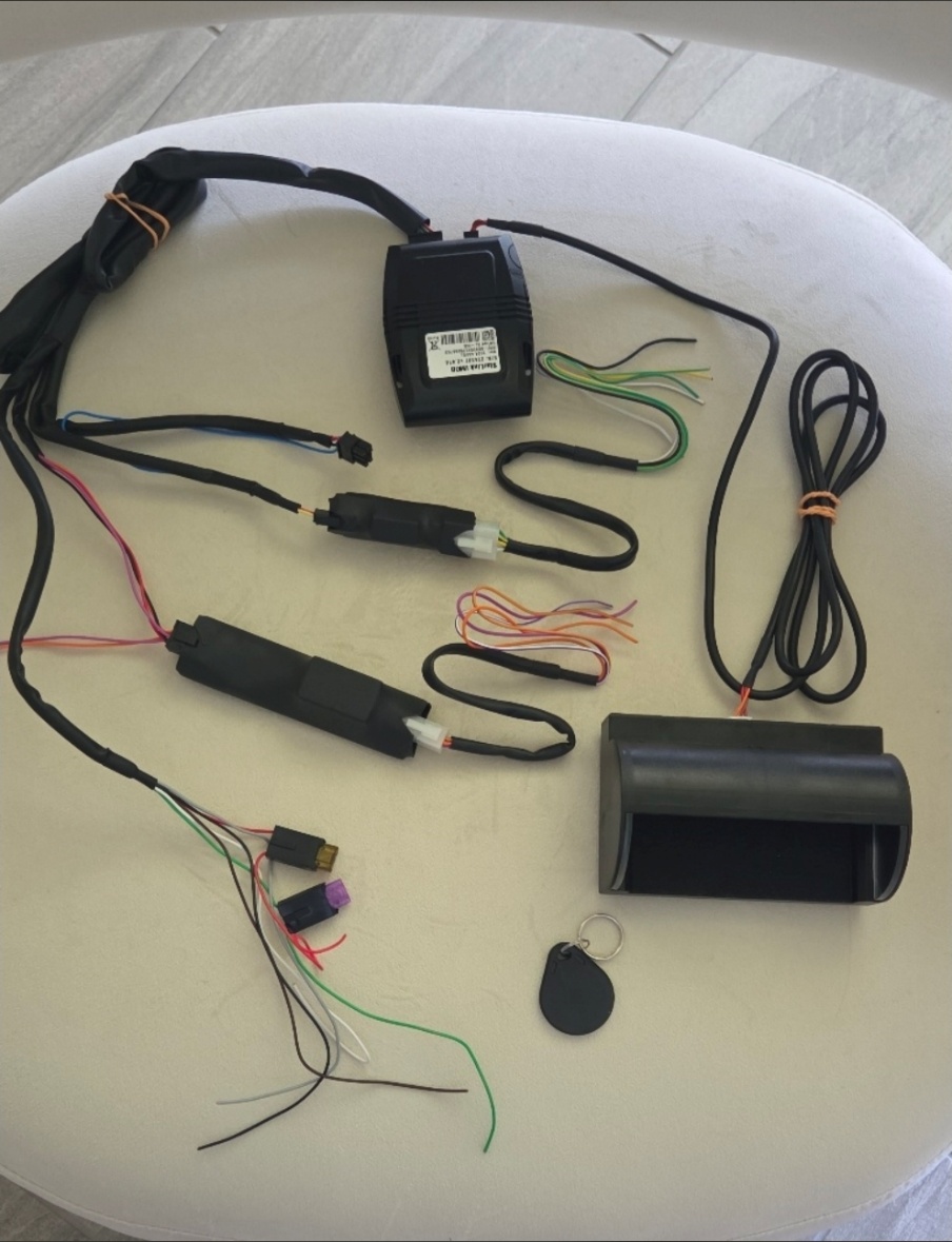
Use this layout and the photos above as your reference for which module connects to what.
Field workflow
⚠️ Installer warning — do not guess connections. The physical location and colors of the vehicle's original wires (CAN lines, Start/Stop button wiring, lock wiring, and power) change completely from one model to the next. Do not guess the vehicle's pinout. Get the exact wire locations for the specific vehicle before you connect anything.
You need two per-vehicle references, and they cover different parts of the install. Get both before you start wiring — they are not alternatives.
- Bench-check the kit first. Assemble the full system on the bench using the quick-connectors and the photos in this guide.
- Then gather both references below for your exact year, make, and model.
Reference A — Ituran USA SMS map (for the immobilizer)
Use this to wire the immobilizer and StarLink power. Contact the Ituran USA support line with the exact year, make, and model. Support texts a link directly to your phone; open it to see the exact electrical map for that car, including:
- The exact starter-motor cut point (conventional-key vehicles) or Start/Stop button circuit (keyless vehicles)
- StarLink power and grounding points
Reference B — iDataLink pinout (for the iDataLink module)
Use this to wire the iDataLink module — door lock/unlock and the CAN connection. Open the iDataLink resource for the vehicle and look up the 10-pin connector pinout for that specific year/make/model. This tells you where to find the vehicle's CAN twisted pair for the iDataLink Brown/Red (CAN H) and Brown/Yellow (CAN L) wires, and the original lock wires.
Use the wiring diagram below as a reference for the StarLink connections (immobilizer, door status, CAN, ignition, power) while you work.
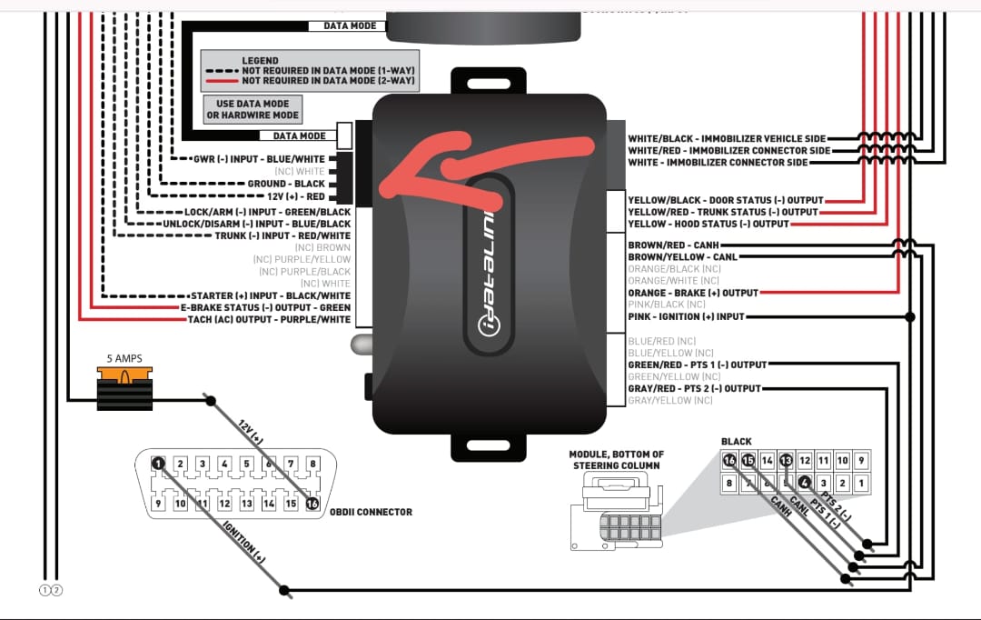
Mounting the Key Holder
The Key Holder must be installed inside the glove box, mounted firmly, flat, and out of sight. Attach the RFID Tag to the vehicle's original key so it cannot be removed — the Tag and the key stay together permanently. When the key with its Tag is dropped into the cradle, the Key Holder detects it by proximity and reports the return to the StarLink over LIN.
Final tests
Do all of this before you close up the vehicle's panels:
- Make all connections and double-check them against both vehicle references (the Ituran USA immobilizer map and the iDataLink pinout).
- Mount the Key Holder in the glove box and confirm it detects the key with the Tag attached (present vs. absent).
- Use the test app to validate lock / unlock and engine block functions over both cloud and Bluetooth.
- Confirm GPS location and cellular reporting are live.
- Only after every function passes, route, secure, and reassemble the panels.
Mob-Full only: CAN-Bus telemetry (optional)
This section applies to Mob-Full. It does not apply to Mob-Connect.
With Mob-Full, the StarLink reads telemetry directly from the vehicle's CAN Bus and reports it to the cloud: odometer, fuel level, driving speed, RPM, VIN, and — on electric vehicles — range and battery level.
This telemetry uses the StarLink's CAN Bus feature, which is only used on Mob-Full and is not used on the other product. Wiring it is not mandatory for the installer: you can complete a fully functional Mob-Full install (tracking, doors, immobilization, key custody) without it. Be aware that adding the CAN telemetry connections is noticeably more complex and higher-risk, so only take it on with the correct per-vehicle CAN map in hand.
Reminder: CAN wires are tapped, never cut. Connect the iDataLink Brown/Red (CAN H) and Brown/Yellow (CAN L) wires to the vehicle's CAN twisted pair only at the points given on your vehicle map.
Still need help?
Contact [email protected] — include your order number and vehicle VIN if applicable.